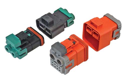
Lock design Connector provides primary self-locking and secondary enhanced self-locking
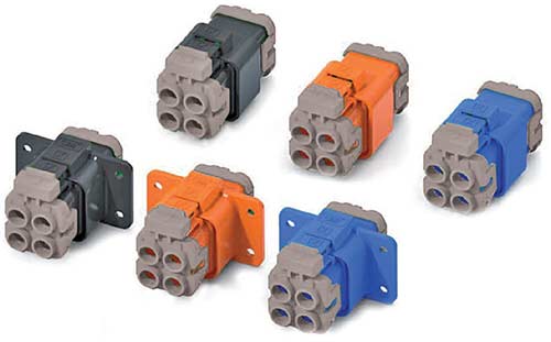
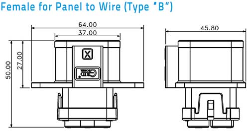
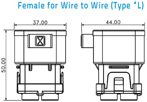
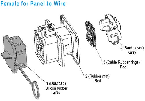
Wire to wire and Wire to panel choice Wire to wire, wire to panel design
Touch safe interface To minimaze potential contact with life circuit
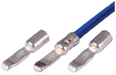
Flat wipping contact technology Flat wipping contact technology, low cost design and high efficient
IP67 Rating water proof IP67 water proof design, and provide connection and disconnection water proof design for panel side. More safety for power equirement IP rating application
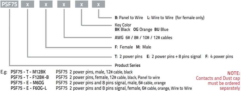
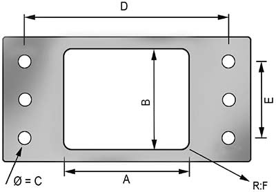
HOW TO DEFINE CONNECTOR HOUSINGS
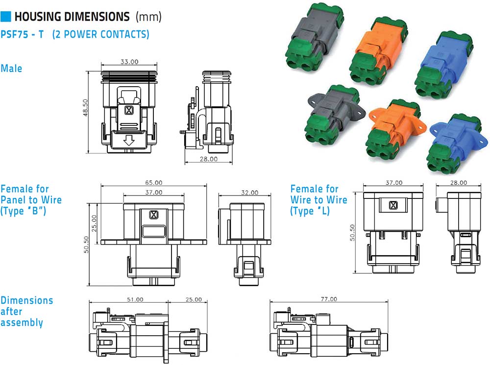
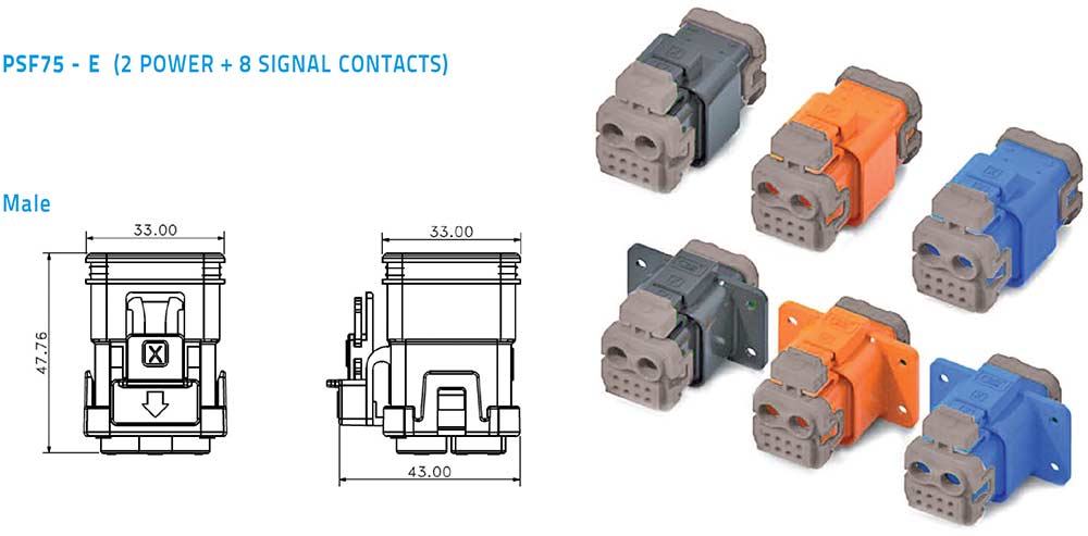
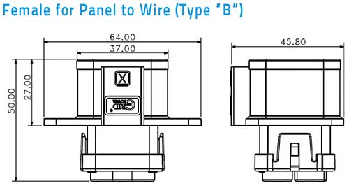
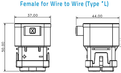
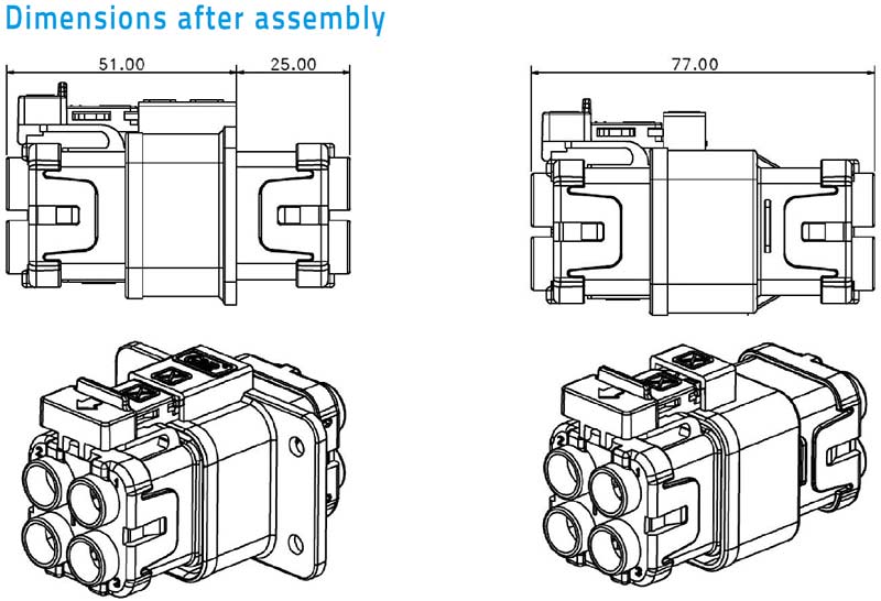
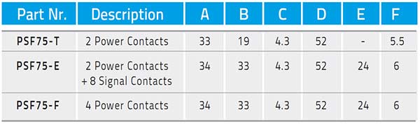
Housing Dimensions (mm)
Housing Dimensions (mm)
Housing Dimensions (mm)
Recommended panel coutout (mm)
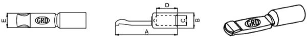
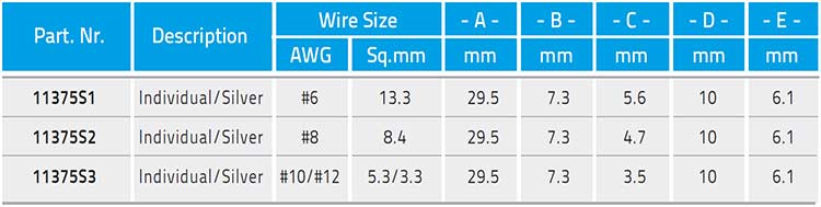
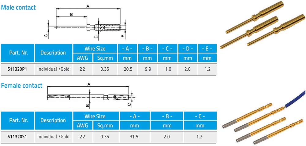
Power contacts
Signal contacts
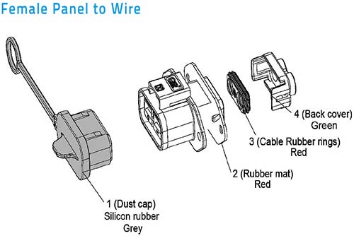
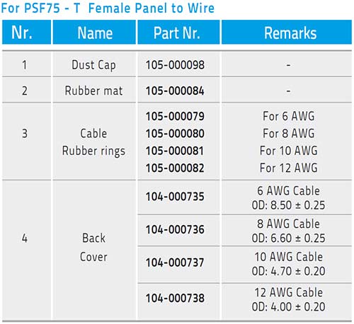
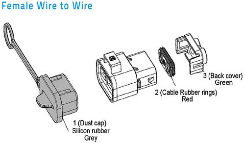
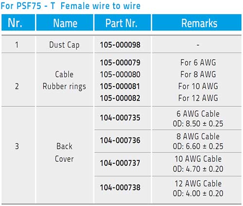
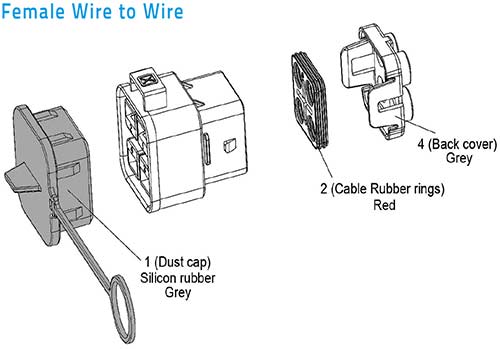
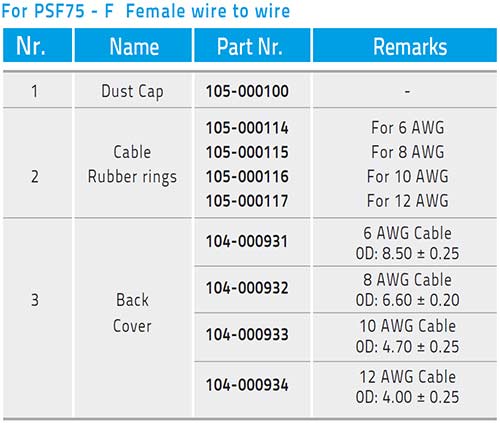
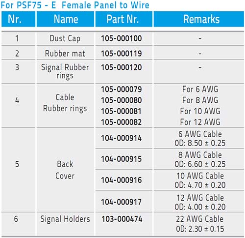
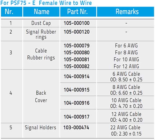
Housing spare parts and dust caps
Housing spare parts and dust caps
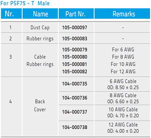
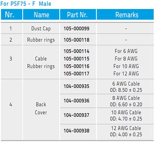
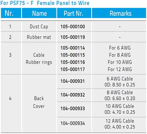
HOUSINGS SPARE PARTS AND DUST CAPS
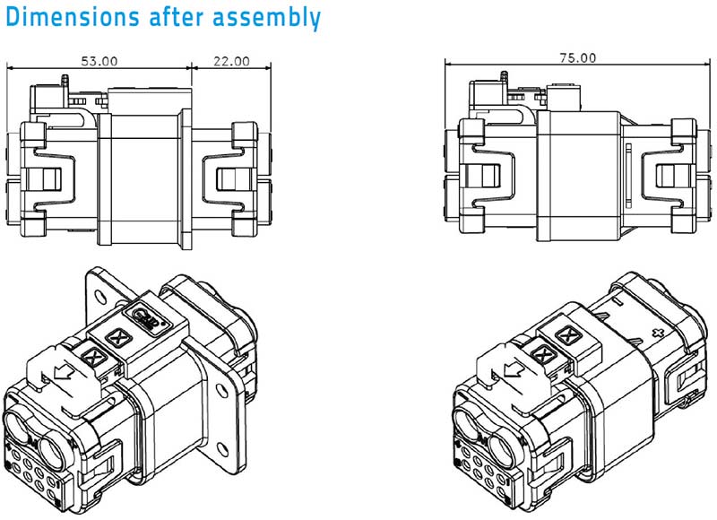
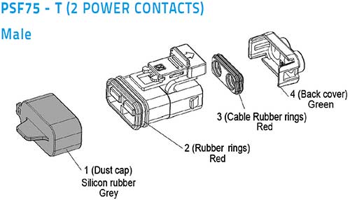
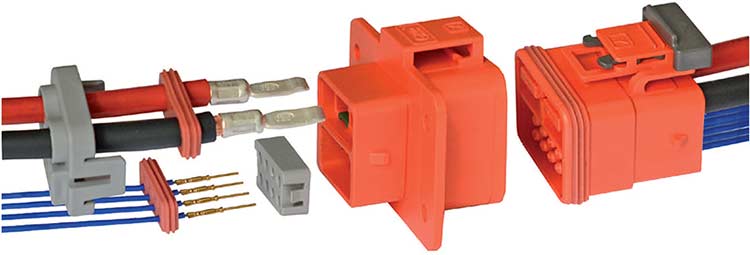
PSF75 CONNECTOR ASSEMBLY
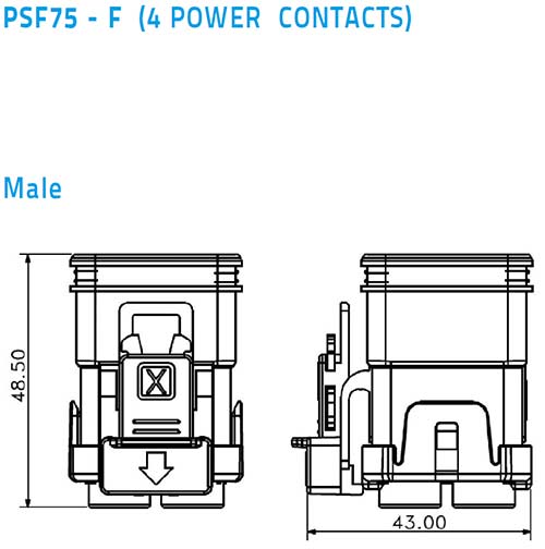
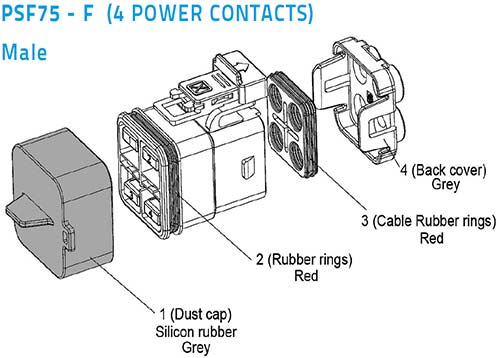
PSF75 2 Power and 4 Power Contacts
Power cables must be inserted thru Back Cover (4-3) and “Cable Rubber Ring” (3-2)
Strip cables and wires and crimp contacts then insert them into housing, according position numbers molded on housing. Check that contacts be locked by springs
Push“Cable Rubber Ring” (3-2) into housing and lock Back Cover (4-3)
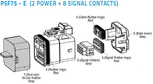
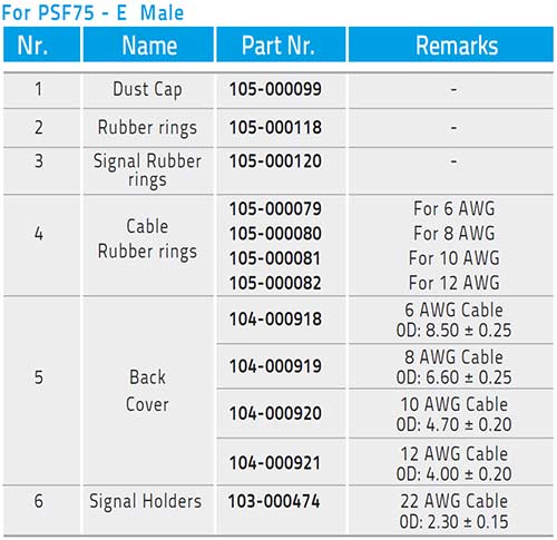
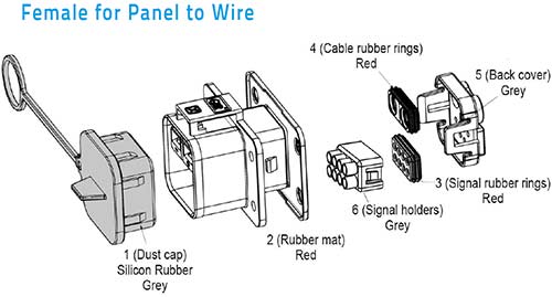
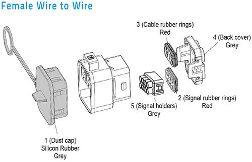
PSF75 2 Power + 8 Signal Contacts
Power cables and signal wires must be inserted thru Back Cover (5-4),“Cable Rubber Ring” (4-3) and Signal Rubber Ring” (3-2)
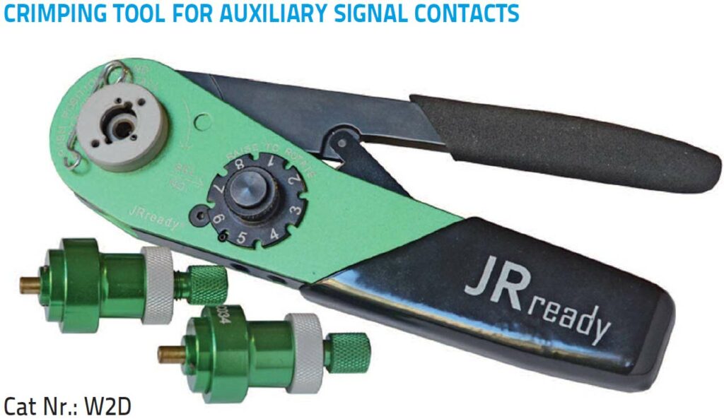
Strip cables and wires and crimp contact
Insert Power Contacts according positive and negative polarity indicated on housings
Insert male Signal Contacts into“Holder” (6) positioned into female housing and female Signal Contacts into“Holder” (6) positioned into male housing
Push“Cable Rubber Ring” (4-3) and Signal Rubber Ring” (3-2) into housing and lock Back Cover (5-4)
PSF75 CONNECTOR DISASSEMBLY
PSF75 2 Power and 4 Power Contacts
Remove Back Cover (4-3) and “Cable Rubber Ring” (3-2) and pull back them along cables
Remove Power Contacts simply with a small screw driver pushing down retaining contacts springs and pull cables
PSF75 2 Power + 8 Signal Contacts
Remove Back Cover (5-4) ,“Cable Rubber Ring” (4) and Signal Rubber Ring” (2-3) and pull back them along cables and wires
To remove Power Contacts same procedure as above point 2
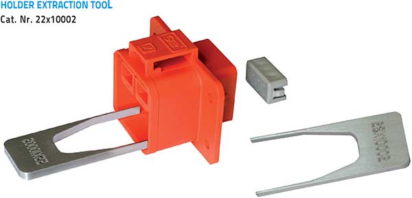
To remove Signal Contacts it is necessary to extract“Holders” (6) from housings using a special tool (see “Tooling” section). Insert tool front housing then pull out Holder, eventually using a little plier to extract Holder and contacts
In case of repair it is necessary to replace Holder and contacts be in touch with ITC for further information